

Old-timers amongst my readers will likely get the second degree reference to that seminal book by Jack Herer, a much recommended read even today. The book title was adapted from an Andersen’s fairy tale, which allegory Herer employed to portray hemp prohibition.
The idiom is used to describe a situation where a widely accepted belief is exposed as a fraud or delusion. In our context, the belief would be that all vaporizers are inherently safe, until someone realizes that they might not be after all.
On the old FC forum, health-conscious members including myself always tried to expose the use of unsafe practices or materials and manufacturers trying to cover their mistakes up.
To follow that tradition and in order to cut through any speculation before it might even become rampant, and also because you should not take what I (or anyone) claim as face-value, I decided to be upfront and show you Ubik entirely naked, in total transparency.
The goal at this point is not to show you a full “behind the scenes” of how I craft Ubik, as it would be much too long but it might come in due time when the pressure on my shoulders drops a bit. I will thus focus only on the important parts regarding safety: materials and the vapor path.
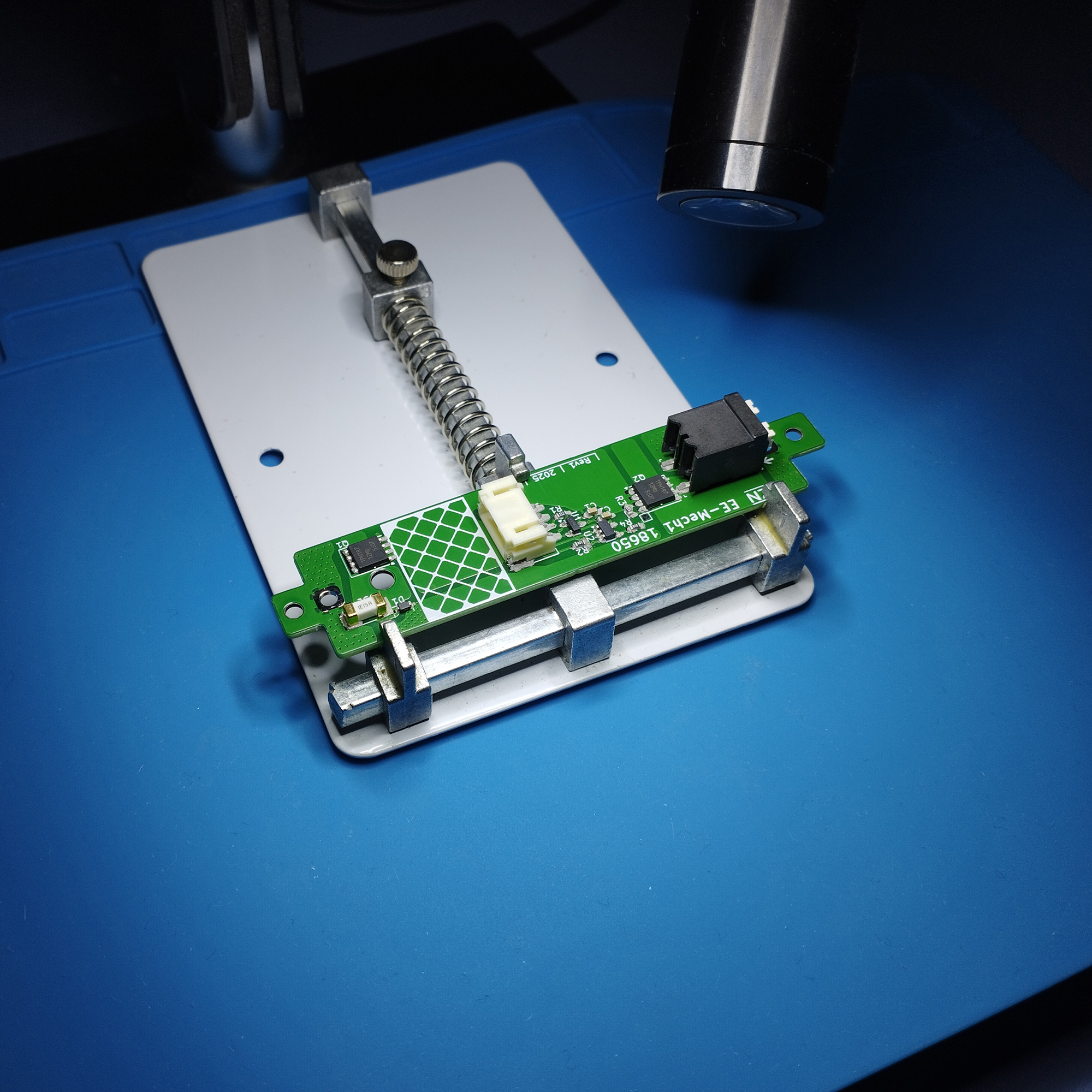
The circuit board is printed using a lead-free process. I apply a lead-free solder paste then hand-populate it with components devoid of harmful substances, complying with the EU RoHS and REACH directives. At the end I wash them thoroughly to remove any flux and solder residues, using hand scrubbing and a long dip into an ultrasonic bath.
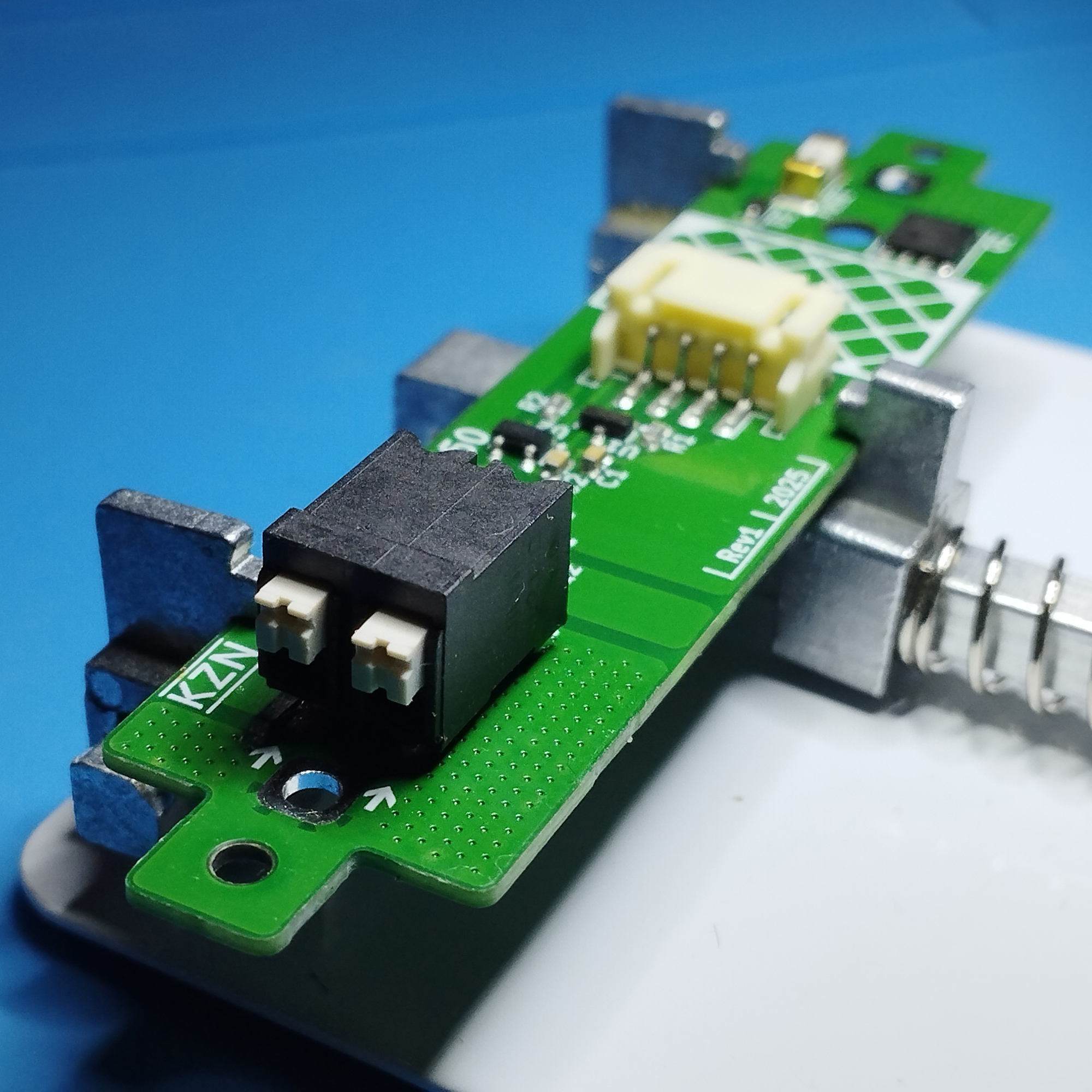
The black component in the above picture is the spring terminal into which the heater module electrodes (legs) are inserted. While the white one is the female connector where the trigger button cable is plugged.
After all surface-mount components are reflow-soldered, I hand-solder the battery holder on the other side, again using lead-free solder.
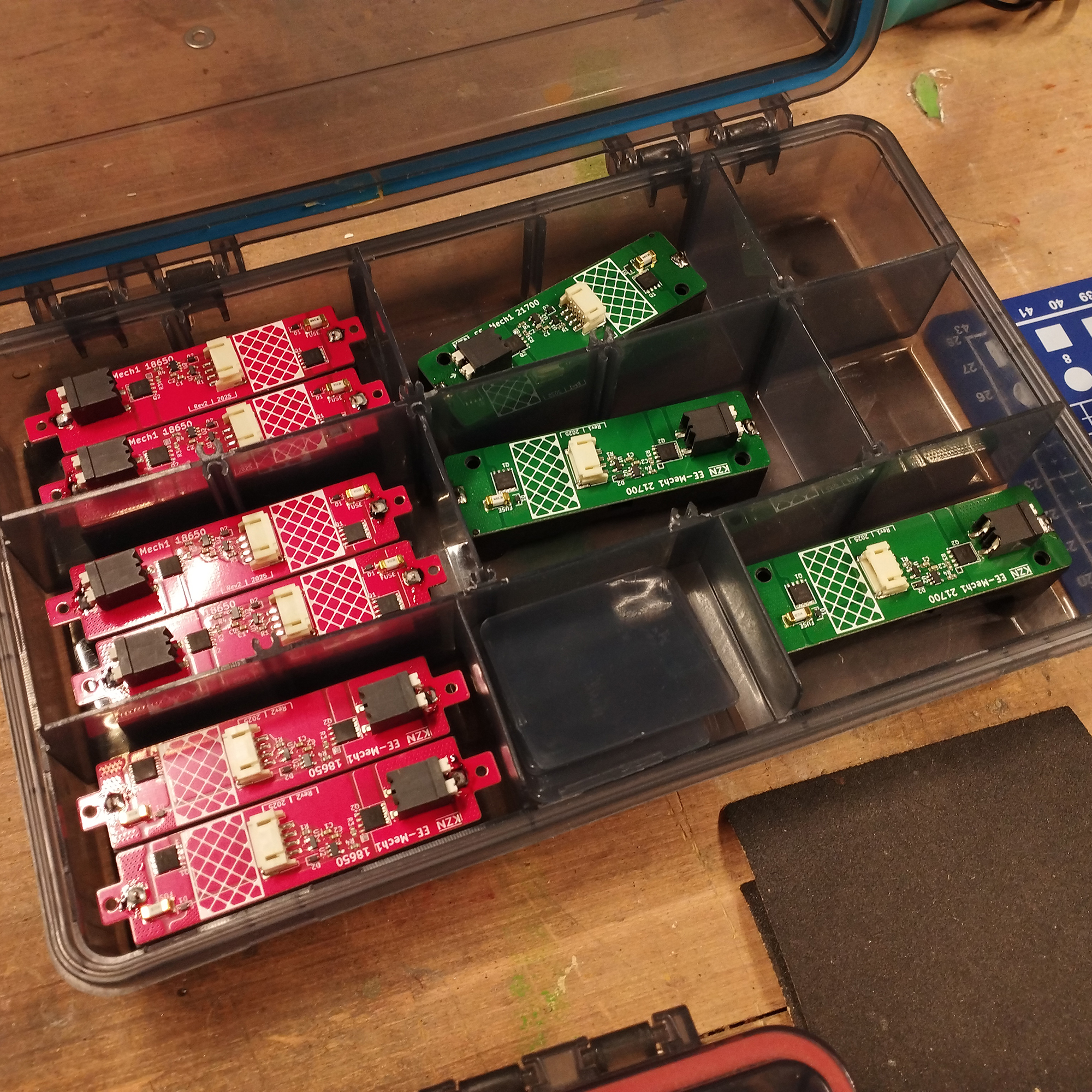
The first 10 boards for each Ubik cell class were green and were used internally and for units handed out to my testers. The next 50 PCBs for each size are a limited edition red color. And later units will sport black circuit boards.
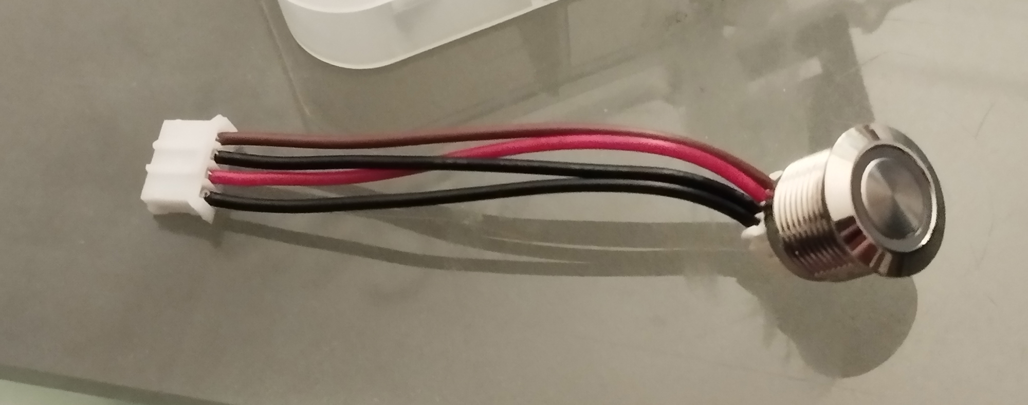
The trigger button itself is secured to Ubik wooden body using a hex nut. The male connector at the extremity of the button cable assembly is crimped. It plugs into the white female connector we have seen on the circuit board earlier.
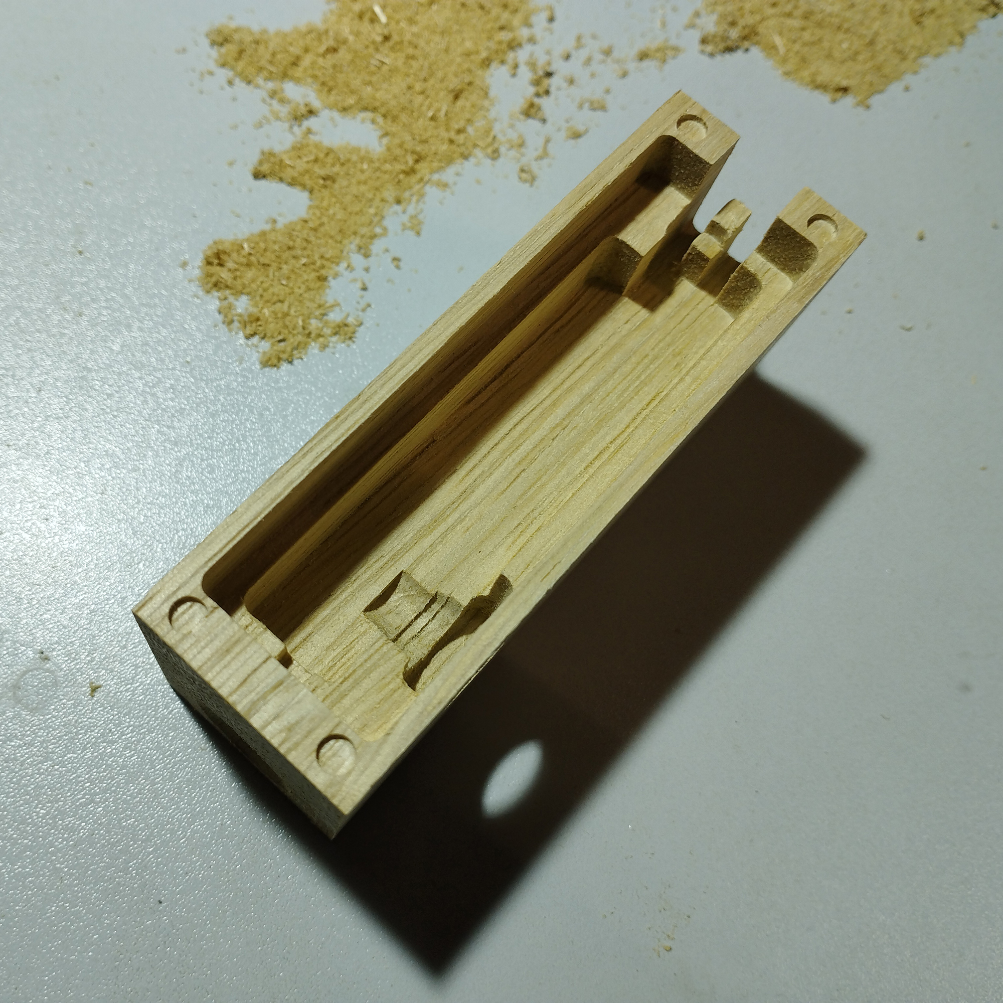
The electronics reside entirely in a dedicated compartment, milled directly inside Ubik wooden body. This compartment is distinct from the vapor path and the only communication between the two is through a shallow channel where the heater electrodes pass.
This channel is just behind the center pillar that you can see at the top right in the above picture. The pillar physically prevents the two heater electrodes to ever touch, which would create a short-circuit.
You can also see the 4 holes that receive the magnets. It’s the only place where any glue is used in the whole assembly, and it is not inside the vapor path.
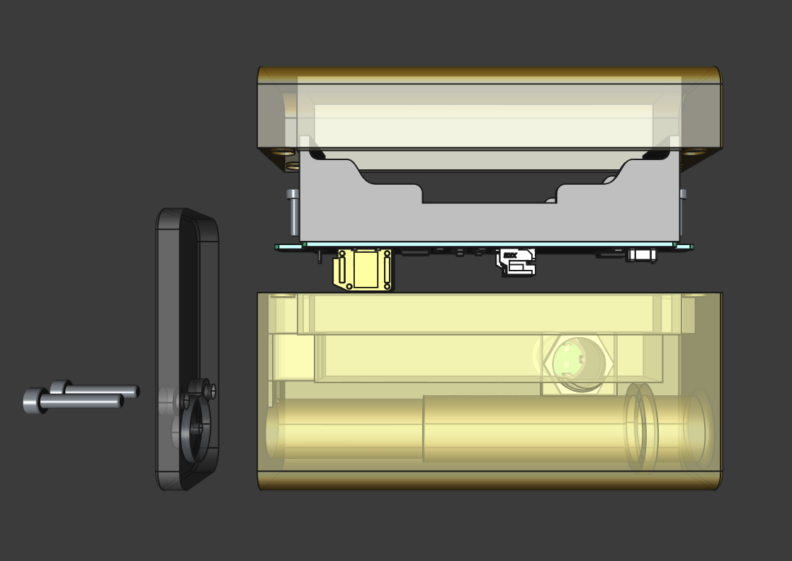
In this first transparent 3D view you can see the 3 main wooden parts (body, door and bottom plate), the PCB and the button, and the 4 screws that hold everything in place.
The only things missing are the heater module and the button cable assembly, for clarity sake.
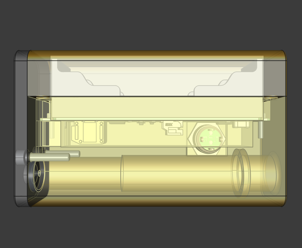
In this second one you can see all components assembled in their final position.
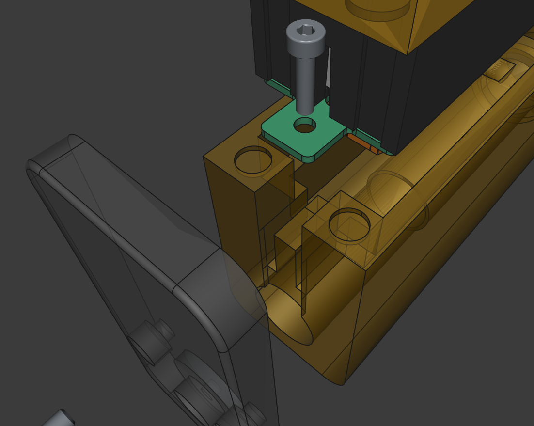
In this detail view you can see the shallow channel in question where the two heater electrodes travel. The electrodes make two consecutive right angle turns.
This is in this channel that the natural cork gasket pieces are positioned in a sandwich arrangement, allowing to isolate the electronics compartment (above) from the vapor path (below).
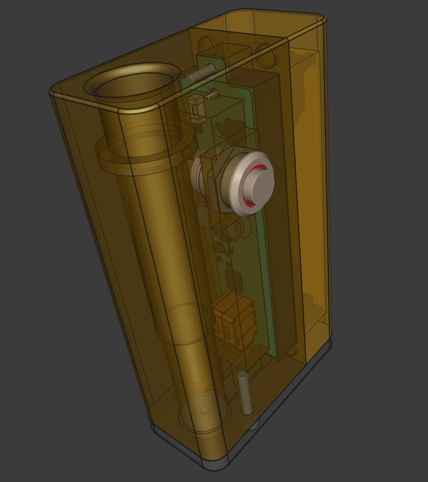
In this last 3D render, you can see in transparency the vapor path itself which would be otherwise complicated to show.
At the top is the entry hole where the glass straw is inserted. The larger diameter groove below receives the food-safe silicone (VMQ) o-ring which holds the straw in place and create an air-tight seal.
The straw inserts 2/3 of the way down until it reaches the stopper, where the hole diameter is slightly reduced. It physically can’t go any further down. This is at this location that the internal SS304 mesh screen is positioned.
Then the narrower diameter section down below is where the heater module in inserted. This entire section is lined by a SS304 foil to isolate the wood from the heat and the vapor path. This foil also acts as an infrared reflector, bouncing some of the energy back into the heater and air stream.
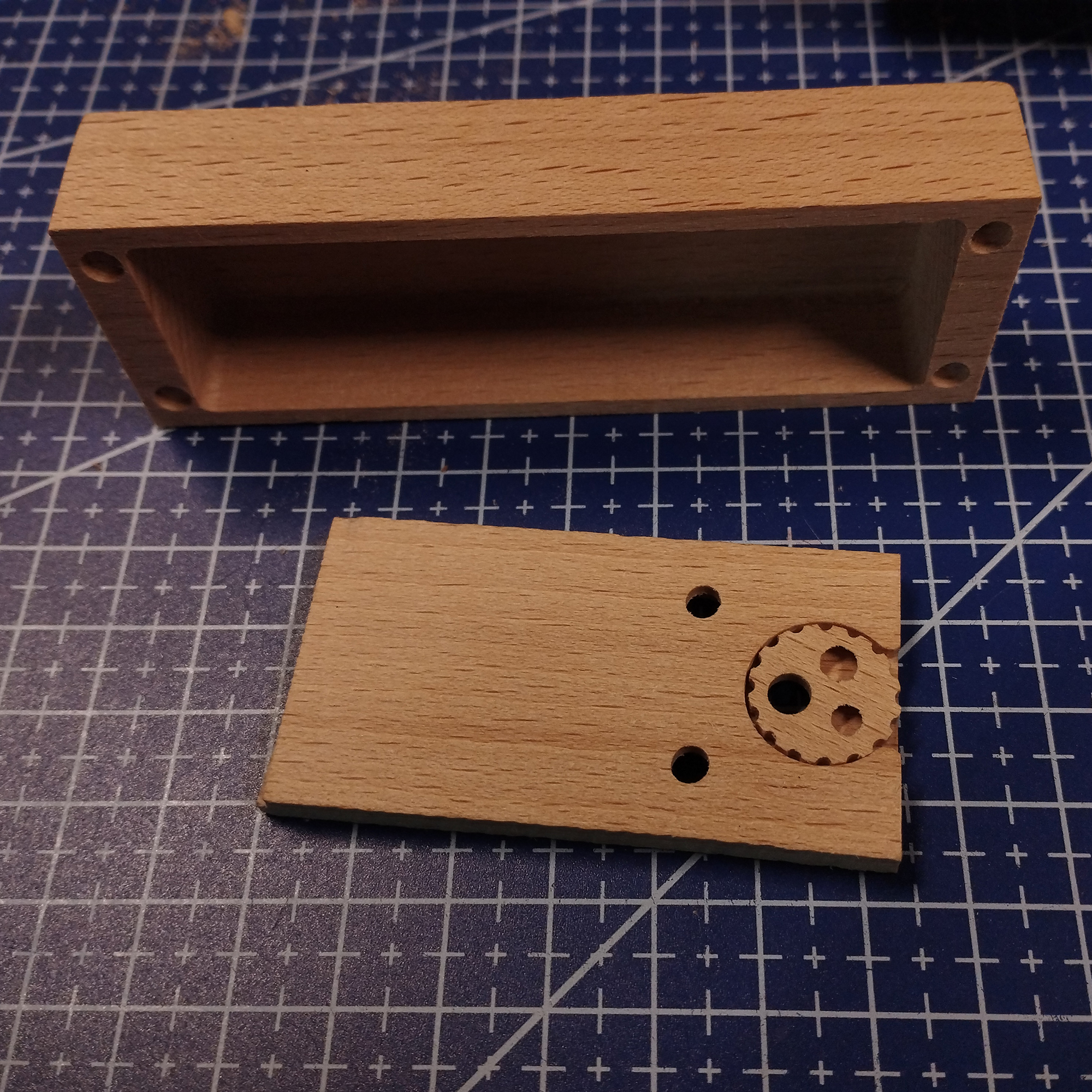
Here you can see the non-visible side of the unfinished bottom plate with the wooden variflow disc. This is the side that mates with the bottom of the body assembly (wood on wood joint).
So if we follow the air from intake to output, it passes through the wooden bottom plate, through the active/selected hole of the variflow disc, then it enters the heater compartment lined with stainless steel, while still cold it brushes past the natural cork gasket and the silver-bronze alloy of the tip of the electrodes, passes through the heater itself, borosilicate glass and again stainless steel but SS430 this time, gets heated up, exits the heater and passes through the internal stainless steel screen, and immediately encounters the tip of the borosilicate glass straw, where the load is inside a second stainless steel basket screen.
From that point the vapor is generated via convection heating and flows only through the glass straw and into your lungs. There is technically some exposed wood in the straw channel between the o-ring and the internal screen, but only residual vapor (if there is any) can go there when you stop drawing. Otherwise this entire zone is under vacuum when you draw.
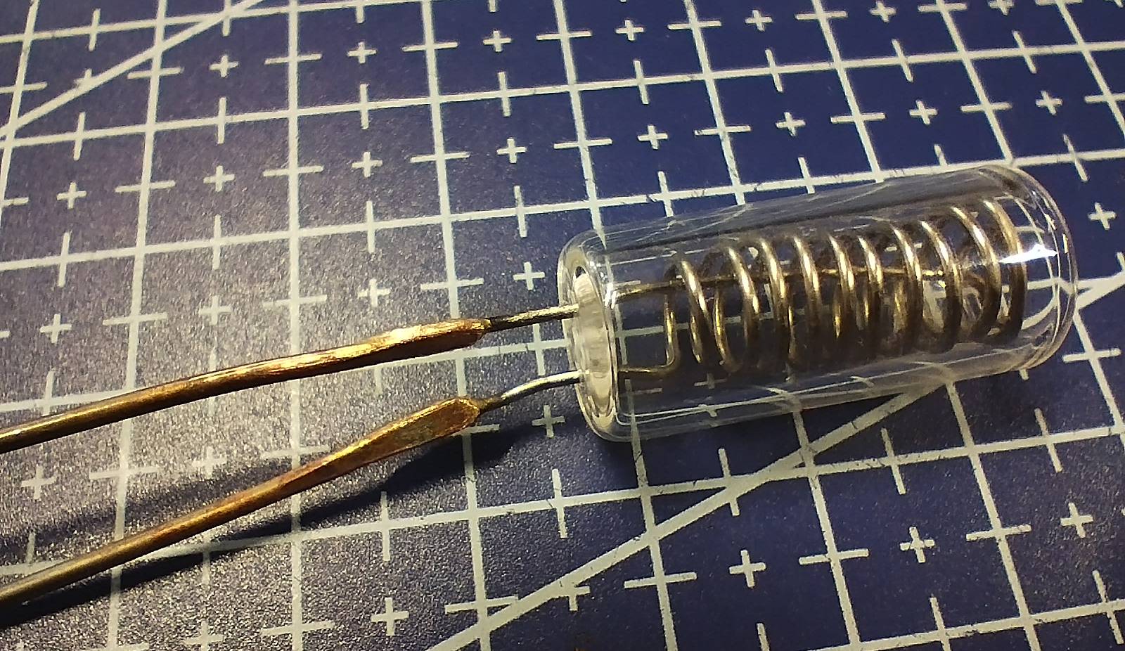
Finally, an entire article could be dedicated to the heater module itself and why this particular configuration was selected amongst many others after so much experimentation, but this is beyond the scope here.
There is nothing particularly fancy to see, just a careful tuning of the relevant design parameters, to achieve enough lag while still being reactive enough for on-demand use, with the use of turbulent flow and of that specific stainless steel alloy.
The heating element is a resistive SS430 wire (without any nickel content), encased inside a borosilicate glass capsule open on the exit end and closed on the other with the exception of 5 intake holes.
To which I perform a silver brazing operation using high silver content solder, with the remaining being copper, to a pair of electrodes made of solid tin-plated copper wire and having virtually no resistance in this application at these current levels.
The brazing technically creates a complex silver-bronze alloy, and the interface between the electrodes and the heating element never reaches temperatures high enough during normal operation to create any concern.
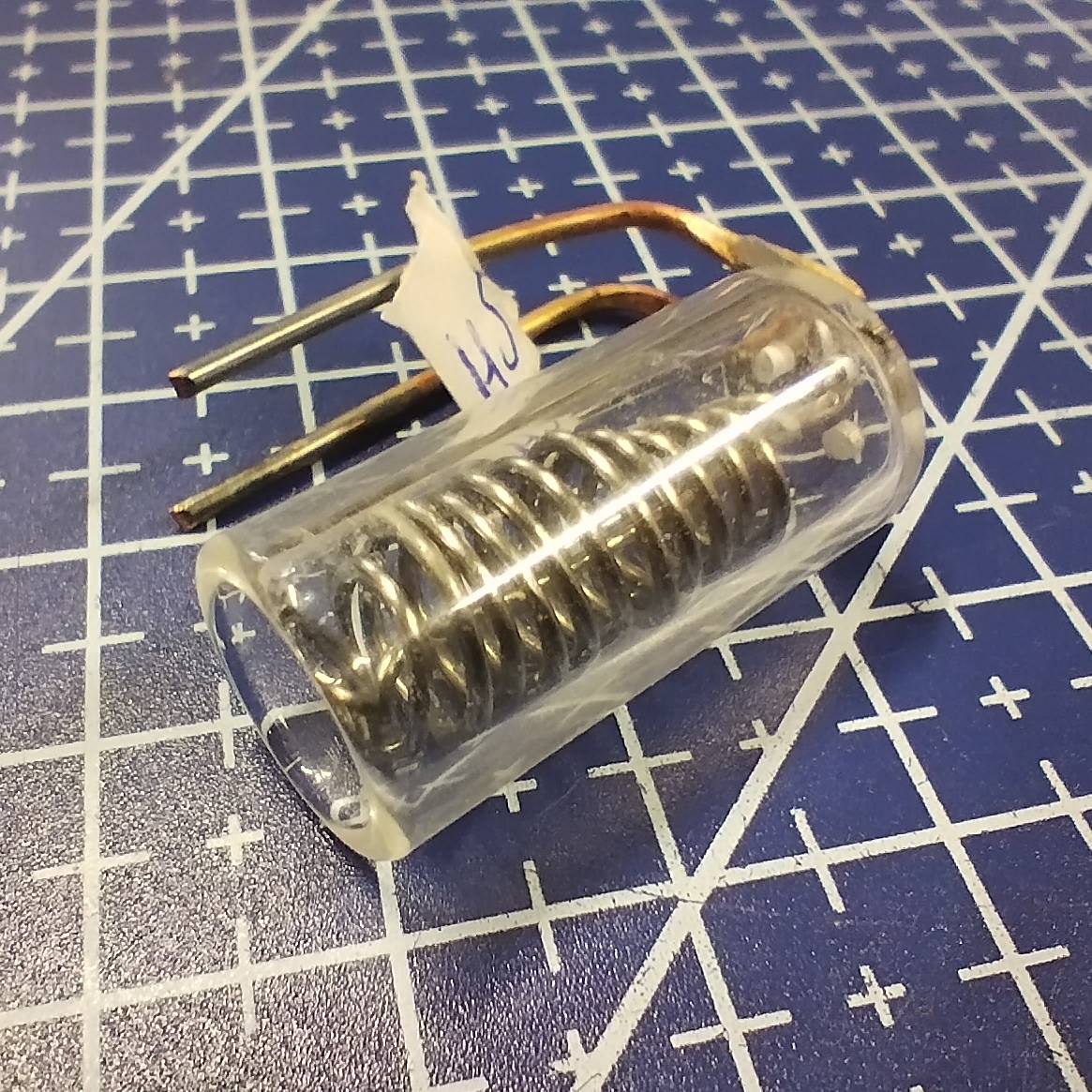
The legs are bent two times, and this is what a complete heater module looks like. Albeit not necessarily with that exact same coil shape, as they are hand-wound. And the paper tag with the heater number is just for identification purpose until it gets installed.
The entire glass capsule is inserted inside the stainless steel lined hole, while at the other end the tips of the legs are inserted inside the spring-loaded terminal on the circuit board.
And voila! That’s about all she wrote! Nothing else to see inside Ubik.